
This is the third article in my TTSH Project series! If you missed any, you can find them here.
A brief word about subtractive synthesis
The ARP 2600, like the vast majority of analogue keyboard synthesizers, uses subtractive synthesis to create and manipulate sounds. This means there are three primary modules at work along the audio path: an oscillator, a filter and an amplifier. I promised to make this series intelligible to non-nerds, and I apologize in advance if I’m dumbing this down too much. But here goes.
The oscillator generates a sound – or what will become a sound when we’re done with it – in the form of an oscillating voltage. The filter is the subtractive component. It filters out (subtracts!) certain frequencies from that oscillating voltage.* If you’ve turned the treble or bass knob on a stereo, you have already operated an audio filter. The amplifier then does exactly what your own stereo amplifier does – it takes that oscillating voltage and amplifies it to the point that it is strong enough to move a speaker back and forth, creating sounds that you can hear.
The power supply, oscillators (there are three), and filter of the TTSH exist on separate boards or submodules. I’ve tackled these first, because once I get to the main PCB there’s not going to be much room on my workbench (dining table). Plus, they make for a nice warm-up before we get elbows-deep in this thing.
Power supply
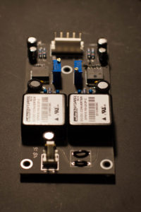
Power supply module
Assembly of the power supply went largely without incident. This is good, because screwing up a power supply can potentially fry other components, kill the operator and burn down the building he died in.** The power supply contains two SMDs (surface mount devices), very small multi-pin devices which, in this case, regulate the power output to the rest of the instrument. Soldering SMDs takes a bit of practise and patience, and I managed to get one of them right the first time. But I like to think you learn more from a flawed build than a perfect one.
Resoldering one of these tiny multilegged beasts is a pain for a couple of reasons. Firstly, they’re super wee, and even the smallest drop of misplaced solder is likely to settle across two or more pins, creating a short, which is bad news. The other problem is that most of these components are heat-sensitive, so while being careful usually means going slow, in this case leaving your hot iron on there for too long can fry things as well.
I was saved, however, by my reflow station, which is a fancy name for a specialized kind of hot air gun. My wife got me one for Christmas and it is dope. It creates a temperature controlled stream of hot air that you can direct at a solder joint, just hot enough to melt the solder – great for removing and replacing SMD components. If you suspect your problem is a bad solder connection, a reflow station might be just the trick to allow the solder to melt and re-settle into a better condition. Happily, that was all it took to fix my problem.
Oscillators (VCOs)
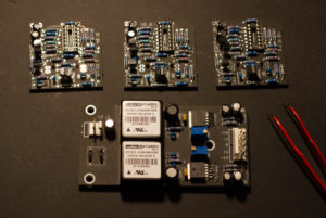
Oscillator modules with power supply
The VCO (Voltage Controlled Oscillator) submodules were assembled without incident. The solder reflow station helped me to install two SMD capacitors on the back of each one pretty tidily, with the addition of a tiny bit of solder paste. I like these little guys; they remind me of the little bite-sized chocolate bars you used to get at Halloween, except they’re not much bigger than a pinhead. We’re going to talk more about the oscillators once they’re wired up and we can have a look at them on an oscilloscope. Assuming they work!
Filter
The filter is where things start to get really interesting. There are many different filter designs in the analogue world. Each filter design can impart a particular character to the resulting sound, and as a result many analogue synthesizers are defined by the type of filter they have under the hood. The Moog filter, designed by Dr. Robert (Bob) Moog in the 1960s, is considered by many to be the gold standard.
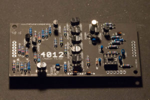
4012 model ladder filter – if you find the problem I found, you get a gold star
Alan R. Pearlman, after whom ARP is named, must have shared that sentiment. The original filter in the ARP 2600 was so similar to the Moog design that Moog eventually threatened ARP with a lawsuit, and as a result the ARP 2600 was produced with two different filter designs: the 4012 “lawsuit filter,” which is very much like the Moog “ladder filter,” and the 4072 “post-lawsuit filter,” which is considered by many (perhaps the same folks who feel the Moog design is the gold standard) to be flawed.
The TTSH panels included a PCB for each filter version. I opted for the 4012. The Moog filter design is referred to as a “ladder filter” due to the ladder-like arrangement of the transistors – which you can see clearly in the photo. These transistors are arranged in matched pairs, the matching of which I discussed in the previous article. It’s worth noting that once you have identified a pair of transistors that behave similarly under similar temperature conditions, it behooves you to ensure that they will be operating at similar temperatures through thermocoupling.
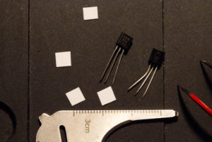
Tiny little pieces of thermal tape
Thermocoupling is a fancy word for making sure that two components are physically connected so that they can exchange heat freely, and thereby stay at the same temperature relative to one another. Thermal paste is a good way to do this, but my local parts supplier was out of thermal paste and I ended up using thermal tape, which is double-sided tape designed for its heat-conductive properties. And if you already love working with double-sided tape, try working with it in 5mm squares for a fun challenge.
On to the main board
Once the submodules were completed, there was no way to put off populating the main board any longer. So be sure to tune in for our next instalment.
*I’m leaving out a bunch of stuff about waveforms and their frequency content. It’s a pretty interesting sidebar, but it’s been covered really well already, and even comes as a nice set of colour posters from the Bob Moog Foundation.
**We’re not actually dealing with mains AC here because we have a 24 VDC external adaptor, but still, measure twice and cut once as they say.