
The Elektron Octatrack (OT) is a powerful little box, and even though the original version is almost 10 years old it’s still a pretty handy device for electronic music performance and production. Among its many capabilities are those of a looper pedal – but unfortunately there is no pedal controller made specifically for the OT. There are a number of commercially available pedals you could buy to do the trick. But if you’re a wee bit handy you can build your own with a handful of readily-available parts. If you want to skip all the chit-chat and start building, head to the BOM.
I’m going to preface this guide by saying I offer no guarantee that this project will suit your purposes. I’m not an engineer. I have no technical accreditation. I just like making stuff. If you ask me about suitable replacements, wattages or tolerances for any components listed below I probably won’t be able to answer you. In fact, the only reason this isn’t on GitHub is that I don’t even want to accept that much responsibility for this project. But it worked for me, and if I can make it work, anyone can.
Basic functionality
What we’re building is a box with five switches, each of which will send a MIDI control message to the OT to control its looping functions. For full details, check out section 17.1.5 of the v1.31 manual, “Controlling the Pick Up Machines With a MIDI Foot Controller.” These five functions are:
- Initiate combo recording
- Toggle play/stop
- Sync to active pickup machine
- Previous track
- Next track
The OT lets you use either MIDI note events or control changes for these messages. I prefer control changes, because it is possible to have all 16 MIDI channels in use at once on the OT, and I don’t want to be worried about sending note triggers to an active channel inadvertently. This is super easy to change in the software you’ll be using, and I’ve given you two versions to choose from just to make things easier.
I’ve built my box with two MIDI ports, one IN and one OUT. The MIDI code that we’ll be uploading to our Teensy defaults to MIDI THRU ON, which is ideal for this application. This way, if you put your pedal in the MIDI chain between the MIDI OUT of your controller keyboard and the MIDI IN of your OT, the Teensy will merge those two data sources together.
The Teensy-LC
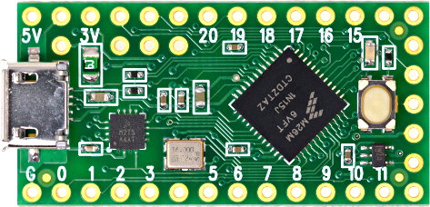
Those switches will be connected to a Teensy-LC USB Development Board. This is a small, low cost (LC) processor that runs Arduino code. They are very inexpensive and well-suited to MIDI applications. From there, all we need is power, a couple of MIDI jacks, a handful of inexpensive components, and some free time.
Most of this design is based on information I found on the PJRC website (manufacturer of the Teensy), so if you’re not familiar with the Teensy, you can head over there for the details on power, connecting MIDI jacks, and uploading software to your device.
BOM (parts list)
Here is what you’ll need to build your pedal.
- A Teensy-LC USB Development Board with 2 x 14 header pins – some places will sell you the Teensy with the headers already soldered on if you prefer
- 5 momentary SPST switches
- 1x LED and appropriately-sized resistor
- 1x pedal enclosure – I used a 1590DD Hammond clone
- 2.1 mm DC Power Jack (if you want to use an adaptor, which I would recommend)
- 1x 5v power supply with 2.1 mm barrel connector (current requirements will be minimal, so 300ma is plenty, but most adaptors you’ll find are at least 1000ma which is fine), or 3 AA batteries in an enclosure, or both
- 1x small prototyping board (0.1″ spacing, I used this one)
- 2x MIDI jacks (5-pin DIN, panel mount) – I like these ones but you can certainly find cheaper options
- 1x 6N138 opto-isolator (for MIDI input)
- 1x 8-PIN DIP socket for your opto-isolator to sit in
- 1x 1N4148 diode (for MIDI input)
- 1x 220 ohm resistor
- 1x 470 ohm resistor
- 2x 47 ohm resistor
- 1x 0.1 µf ceramic capacitor or equivalent
- Hookup wire
- 4x M3 screws, nuts and standoffs for mounting the protoboard to the enclosure – 1/4″ standoffs should do it
- 4x Adhesive rubber feet
- 1x latched SPST power switch (if you’re using battery power) – I recommend something round just because it’s easier to drill a hole than cut a rectangle and I’m lazy
- 1x 1N5817 diode (if you’re using battery power)
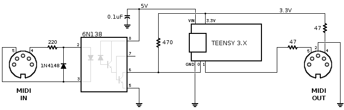
Wiring it up – MIDI
I didn’t put a breadboard in the BOM but it’s not a bad idea to get one and make sure this all works before you solder it all together – particularly if this is your first time doing this sort of thing. You may want to take a moment to figure out where the protoboard is going to fit in the enclosure, and use it as a stencil to mark where your screw holes should go for mounting. That’ll be slightly trickier if you solder a bunch of stuff to it first.
Now solder the header pins on the Teensy if they didn’t come attached. Use your protoboard or breadboard as a guide to ensure they’re going on straight. Don’t melt your breadboard though! Deftly solder one pin in each corner and then remove it from the breadboard to finish the rest.
I’m just going to drop the PJRC MIDI diagram here rather than redraw it. This is where most of your passive components end up. Wire this up on your breadboard, or go ahead with the protoboard if you already know what you’re doing. Click the image to get to the source if you have any questions. It says Teensy 3.x here but the connections are the same for the LC.
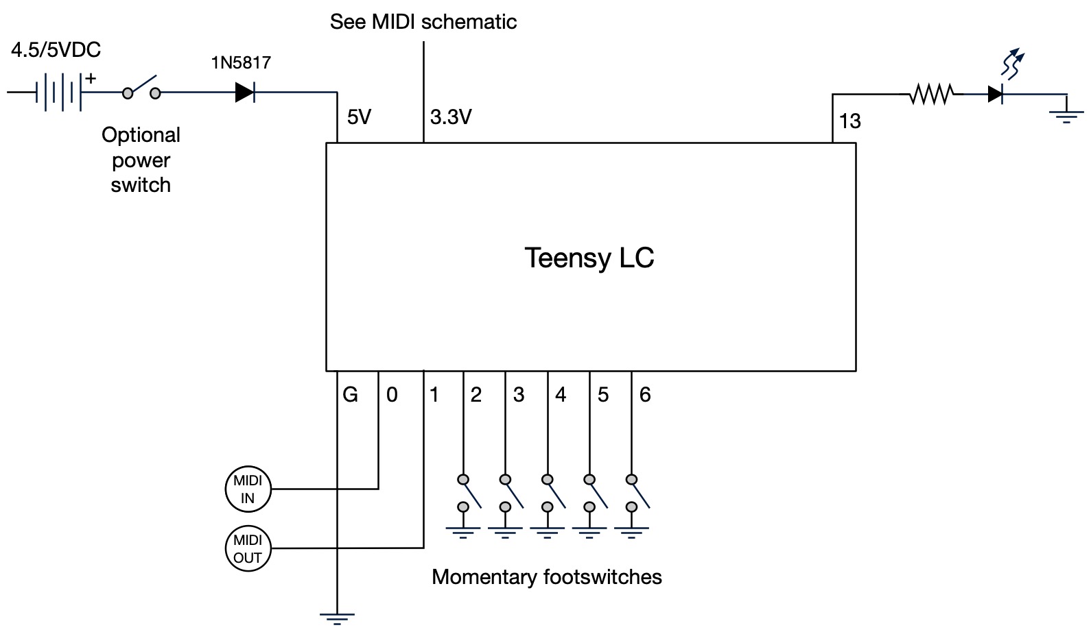
Wiring it up – the rest of it
From here on, things are pretty simple compared to the MIDI business. Switches go on pins 2 through 6. LED goes on pin 13. If you didn’t get the LED with the pre-installed resistor, try 470 ohm and see how you like it. Lower values will get you a brighter light. Positive lead from your power supply goes to 5VDC on the Teensy, and negative goes to ground on the other side. But don’t power it up before you install the software.
Install the software
As I mentioned earlier, you have two options for the code, both of which are in this zip file:
- Buttons_DIN_MIDI.ino will transmit MIDI notes 60, 64, 68,69, and 71 when the respective buttons are pushed.
- Buttons_DIN_MIDI_CC.ino will transmit the corresponding messages on MIDI Controller 59.
You’ll need the Arduino IDE with the Teensyduino add-on to install the software. You’ll want to install the MIDI Library and the Bounce2 Library which can be done through Sketch menu > Include Library > Manage Libraries. If you don’t have the libraries installed the app will give you an error message when you try to compile. NOTE: An earlier version of this post suggested installing the original Bounce library because that’s what I used when I put this script together several years ago. I’ve decided that creates more problems than it solves, so I’ve updated the script to use the current Bounce2 library, which should work fine.
The code is currently set to transmit on MIDI channel 1. If you have your Octatrack set to a different Auto Channel, enter the channel here:
// the MIDI channel to send messages on
const int channel = 1;
About that power trace
The PJRC website is great, but they do make a bit of a fuss about cutting the 5V pads apart, which I’m sure you absolutely need to do if you think you’re going to accidentally hook up the USB to your computer without disconnecting the power. I say how about you just never do that, and leave the trace alone, because if you cut it you’ll always have to power it externally, even when uploading code, which can be a pain.
Test it
Disconnect the Teensy from the computer and apply power from your batteries or power supply. The LED should light up when any of the 5 momentary switches are pressed. A MIDI monitoring app would be handy at this point if you have one, so that you could see exactly what’s happening from the OUT port. But if the LED is blinking when it should, and nothing is smoking, you may be ready to hook it up to your Octatrack and try it out.
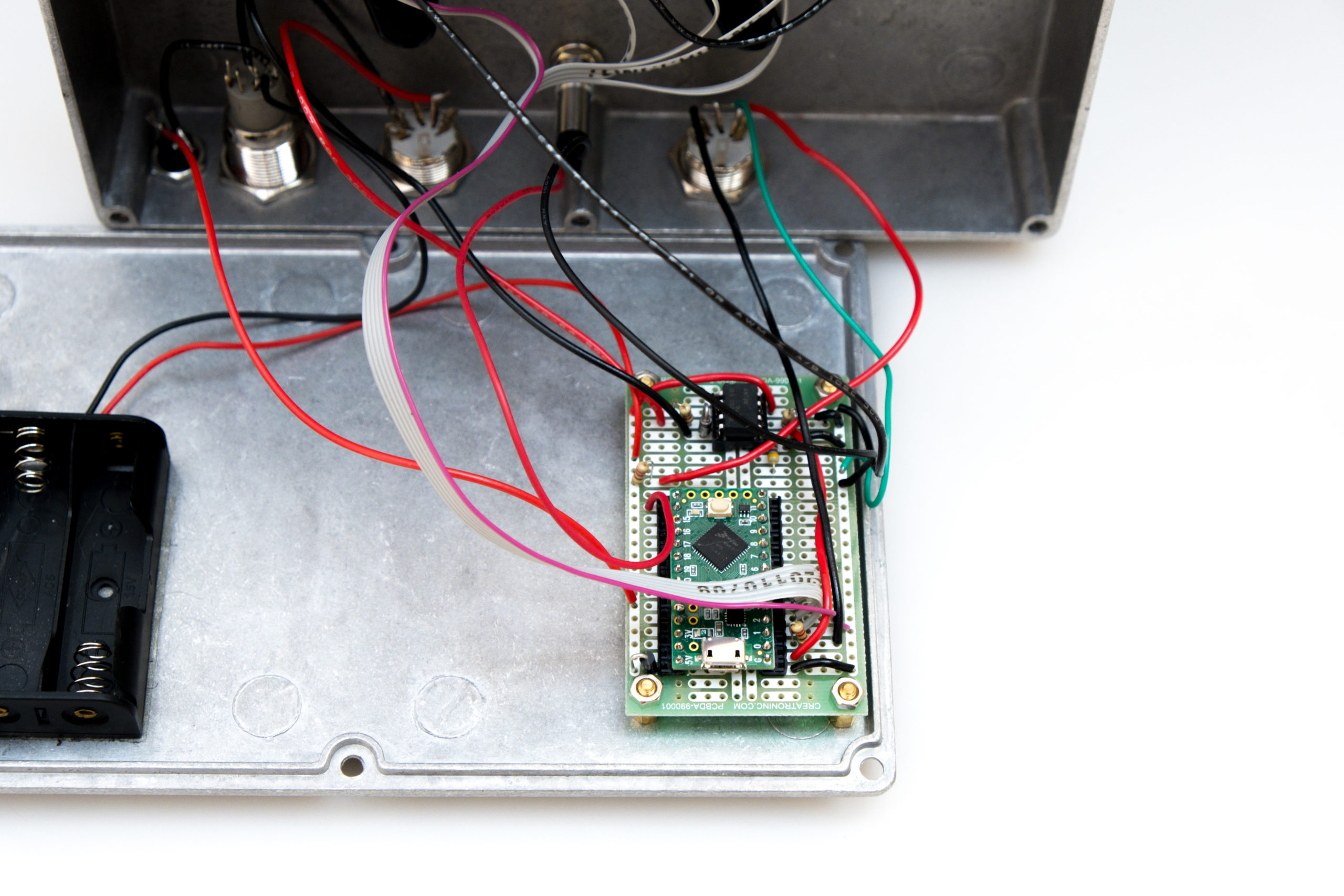
Box it up
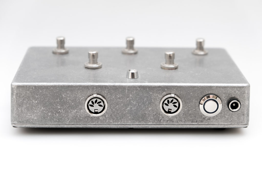
Once everything is working the way you want it to, it’s time to drill some holes in your enclosure and install the hardware. Here is the template I used; if you got the same switches, enclosure and LED that I did, everything on the front panel should be about the right size (measurements are in mm). Same goes for the DC input on the back, and if you got these nifty screwless DIN connectors those should should fit pretty well too. But you know what they say, measure twice, drill once – so double-check your diameters before cutting any metal.
Make some loops
Now go have fun with it, and give me a credit in the liner notes. Just kidding! What are liner notes?