
This is the second article in an ongoing series about my TTSH project. If you want to start from the beginning, go here.
The TTSH is the first project I’ve built that called for matched transistors. There are plenty of articles online telling you how to match transistors (more on this shortly) but relatively few telling you why. And often the answer I found to why is “because they are not matched to a high enough tolerance from the supplier” – which I suppose is unarguable… but still doesn’t really tell us the consequences of not matching your transistors.
What I have learned (and keep in mind if this seems vague it reflects my current understanding of the situation) is that if you have unmatched transistors in certain audio circuits they may behave slightly differently from one another, producing slightly different voltages, particularly under varying temperatures. This can lead to things like DC offsets that could cause “pops” or “thumps” where you don’t expect them, distortion, tuning problems (in the case of VCOs) and so forth.
The good news is that today’s manufacturing processes have much higher tolerances than they did when Bob Moog was designing synthesizers.
The bad news is that there will still be some outliers so you’re going to have to check them all anyway.
The good news is that Thonk sells matching pairs just for people like me who are building a TTSH.
The bad news is that when I was ordering my parts they were out of stock of 9 of the 15 pairs that I needed.
It’s not really bad news of course, I’m doing this to learn stuff, so I might as well learn how to match transistors. As it turns out, it’s not so hard. There are three common methods, in the Goldilocks tradition. The late and much admired Ray Wilson documented a fairly involved method based largely on that of Dr. Moog. The Ken Stone method, by contrast, is pretty quick and dirty, requiring nothing more than a fairly accurate multimeter. The Ian Fritz method, for me, was the sweet spot however, requiring a fairly simple circuit and perhaps something akin to the $25 Radio Shack multimeter that I have in my toolkit.
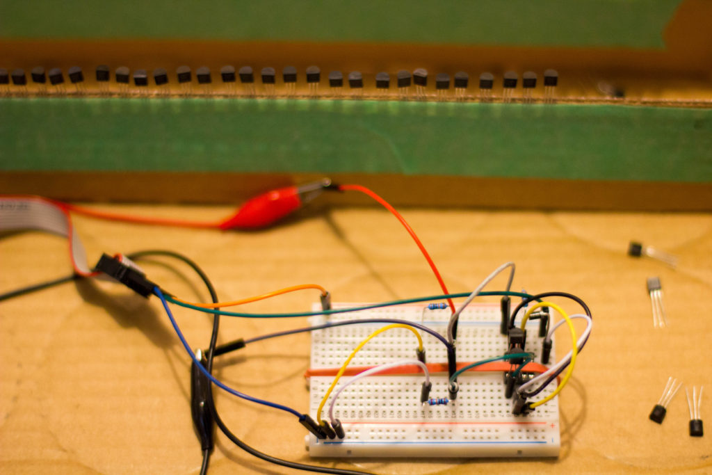
My version of the Ian Fritz circuit, breadboarded
If you clicked the Ken Stone link you’ll notice that I went so far as to set up some transistors for his method before changing my mind. In future I’m going to make sure to buy my bulk transistors on tape. Anecdotal evidence suggests neighbours on a tape roll will be pretty closely matched to start with. The breadboard yielded some inconsistent results, as there is some lead-switching involved, and my IC socket didn’t want to stay seated (hence the somewhat ineffectual rubber band). Further commitment was required.
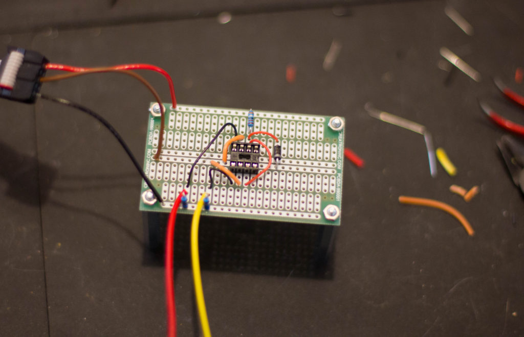
I decided to wire the circuit up on a prototyping board
Above you’ll see the circuit much more securely (if only slightly more tidily) soldered onto a prototyping board. The red and yellow leads at the bottom are alligators that are easily swapped between the meter probes.
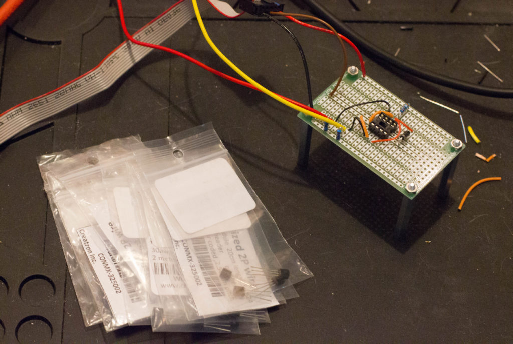
And 9 pairs later you’re done
Once that was set up, and powered by my handy Mutable Instruments Module Tester, the work went pretty quickly. Hidden in this picture is the answer to another common SDIY (Synth DIY) question, “What do I do with all these baggies?” – hang onto a few in case you need to bag your matched transistors.
Read the next article in this series here.